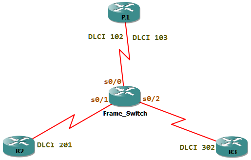
We can configure a Cisco router as a frame-relay switch. The router which I use is a 3700 platform and runs the IOS version 12.4(15)T14. The router will then switch DLCIs between interfaces. For this we have to do the following tasks:
- Activate frame-relay switching.
- Configure interfaces as frame-relay DCE.
- Create frame-relay routes.
First let’s configure the router as to do frame-relay switching
Frame_Switch#conf t

	Frame_Switch(config)#frame-relay switching
Now we have to change the default encapsulation of the WAN interfaces from HDLC to Frame-relay. Then configure the interfaces as frame-relay DCE.
When doing this in lab, we configure the DCE side of the cable to be supply the clock-rate. This Physical DCE has nothing to do with the logical frame-relay DCE. In short the Frame-relay DCE could be either the DCE or DTE side of the physical cable.
The router interfaces by default are DTE. We have to change the interface type to DCE, because only DCE’s will send DLCI. If the interfaces are not configured as DCE, then the line protocol will also get down. Thus we must change them to DCE.
Frame_Switch(config)#interface serial 0/0

	Frame_Switch(config-if)#encapsulation frame-relay

	Frame_Switch(config-if)#frame-relay intf-type dce
The final step is to create the frame-relay routes. This means when a packet is received with a DLCI of X, to which interface must it be switched to. This can be done in two ways, either with frame-relay route command or using the connect command.
First we use the frame-relay route command. When a packet comes from R1 which has a DLCI of 102, it must be sent out to R2 with a DLCI of 201, because R2 owns the DLCI 201. So we must configure the frame-relay route command on the interface where R1 is connected to.
Frame_Switch(config)#interface serial 0/0

	Frame_Switch(config-if)#frame-relay route 102 interface serial 0/1 201
Serial0/0(in): Status, myseq 134, pak size 21

	RT IE 1, length 1, type 0

	KA IE 3, length 2, yourseq 142, myseq 134

	PVC IE 0x7 , length 0x6 , dlci 102, status 0x0 , bw 0
The debug frame-relay lmi output from R1 shows that it received the DLCI number 102.
A frame-relay route command should also be configured on the interface connecting to R2.
Frame_Switch(config)#interface serial 0/1

	Frame_Switch(config-if)#frame-relay route 201 interface serial 0/0 102
Now let’s configure the route between DLCI 103 and 301 which is between R1 and R3 using the connect command.
Frame_Switch(config)#connect R1-R3 serial 0/0 103 serial 0/2 301
Now we can verify the configuration on the frame-relay switch. It must have 4 PVCs, 2 for R1 and one each for R2 and R3.
Frame_Switch#sh frame-relay pvc | include DLCI

	DLCI = 102, DLCI USAGE = SWITCHED, PVC STATUS = ACTIVE, INTERFACE = Serial0/0

	DLCI = 103, DLCI USAGE = SWITCHED, PVC STATUS = ACTIVE, INTERFACE = Serial0/0

	DLCI = 201, DLCI USAGE = SWITCHED, PVC STATUS = ACTIVE, INTERFACE = Serial0/1

	DLCI = 301, DLCI USAGE = SWITCHED, PVC STATUS = ACTIVE, INTERFACE = Serial0/2
The DLCI 102 and 103 is assigned to the interface serial0/0. DLCI 201 is assigned to interface serial0/1 and 301 assigned to interface serial0/2. This means that the R1 must receive DLCIs 102 and 103; R2 will receive 201 and R3 301. They will only receive this DLCIs if the interfaces are configured are frame-relay DCE.
R1#sh frame-relay pvc | include DLCI
DLCI = 102, DLCI USAGE = UNUSED, PVC STATUS = ACTIVE, INTERFACE = Serial0/0

	DLCI = 103, DLCI USAGE = UNUSED, PVC STATUS = ACTIVE, INTERFACE = Serial0/0
The output shows that R1 received 2 DLCIs from the frame-relay switch.
