In traditional physically looped L2 switched networks, the redundancy is removed by the STP algorithm. There we use the PVST or MST to tune that some link are not blocked for a specified VLAN. In a long run this will be a huge administrative burden.
To achieve forwarding over all links in the core, is to use some protocol which has the knowledge of the whole topology and the active links. Examples would be Fabric Path (FP) from Cisco, or the open standard Transparent Interconnection of Lots of Links (TRILL). We could also use the old good MPLS also to achieve this; specifically we will be encapsulating L2 Ethernet frames into MPLS
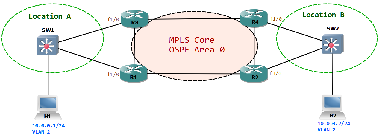
In the below topology we have H1 and H2 belonging to VLAN 2, which are supposed to communicate over the EoMPLS backbone. All of the packets send from VLAN 2 will be encapsulated inside the MPLS payload. At the end we have 2 logical wires or Pseudo-wire between the 2 switches.
For MPLS to work at all we have to take the following points into account:
- Ensure L3 reachability via static routing or dynamic routing.
- Enable MPLS on the interfaces.
- Loopback interfaces on routers to specify the MPLS Label Distribution Protocol (LDP) router-id.
- CEF switching must be enabled for MPLS to work (default enabled).
R1:mpls ldp router-id Loopback0interface FastEthernet1/1 description Link to R2 ip address 10.0.12.1 255.255.255.0 ip ospf 1 area 0 mpls ipinterface loopback 0 ip address 1.1.1.1 255.255.255.255 ip ospf 1 area 0
Ethernet over MPLS could be configured in Port mode or VLAN mode. We will be using VLAN mode as many 802.1q tagged VLAN’s could transit a single link. This means the links from the switches to MPLS core must be in Trunking mode and tagging VLAN ID for frames belonging to respective VLAN’s.
SW1:interface FastEthernet1/0 description Link to R1 switchport mode trunk
Now on the MPLS core router R1, we have to create a sub-interface which will be accepting tagged frames form VLAN 2. The xconnect command will then logically combine the VLAN ID with a logical Wire using the MPLS encapsulation. In our case we use the logical wire (Virtual Circuit) number 2
R1:interface FastEthernet1/0 description Link to SW1 no ip address!interface FastEthernet1/0.2 encapsulation dot1Q 2 xconnect 2.2.2.2 2 encapsulation mpls
Now we can verify the configuration.
R1#sh mpls l2transport vc 2 detailLocal interface: Fa1/0.2 up, line protocol up, Eth VLAN 2 upDestination address: 2.2.2.2, VC ID: 2, VC status: upOutput interface: Fa1/1, imposed label stack {16}Preferred path: not configuredDefault path: activeNext hop: 10.0.12.2Create time: 00:25:04, last status change time: 00:24:16Signaling protocol: LDP, peer 2.2.2.2:0 upMPLS VC labels: local 16, remote 16Group ID: local 0, remote 0MTU: local 1500, remote 1500Remote interface description:Sequencing: receive disabled, send disabledVC statistics:packet totals: receive 990, send 1719byte totals: receive 116638, send 204028packet drops: receive 0, seq error 0, send 0
we can see that the VLAN ID 2 is up. The destination of the virtual circuit is 2.2.2.2. The VC has an ID of 2. When we send a ping from H1 towards H2, the debug output shows the packet transverse.
R1#deb mpls packetPacket debugging is on*Feb 17 17:16:24.618: MPLS turbo: Fa1/1: rx: Len 140 Stack {16 0 255} CW {0 0 0}
The length of the packet is 140 Bytes. This includes the actual ICMP data of 72 Bytes + 8 Byte ICMP header + 20 bytes of IP header + 18 bytes of L2 header including the 802.1q VLAN ID + 8 bytes for MPLS and control header + 14 bytes Ethernet header.
No. Time Source Destination Protocol Length Info10 22:17:56.884 10.0.0.2 10.0.0.1 ICMP 140 Echo (ping) request id=0x0000, seq=1/256, ttl=255Frame 10: 140 bytes on wire (1120 bits), 140 bytes captured (1120 bits)Ethernet II, Src: ca:01:2d:2c:00:1d (ca:01:2d:2c:00:1d), Dst: ca:00:2c:5c:00:1d (ca:00:2c:5c:00:1d)MultiProtocol Label Switching Header, Label: 16, Exp: 0, S: 1, TTL: 255PW Ethernet Control WordEthernet II, Src: cc:0c:11:40:00:00 (cc:0c:11:40:00:00), Dst: cc:0b:11:40:00:00 (cc:0b:11:40:00:00)802.1Q Virtual LAN, PRI: 0, CFI: 0, ID: 2Internet Protocol Version 4, Src: 10.0.0.2 (10.0.0.2), Dst: 10.0.0.1 (10.0.0.1)Internet Control Message Protocol
All of the packets are encapsulated in MPLS packets. There are 2 logical connections between SW1 and SW2, one will still be blocked via STP. This link could be used as a backup link. We can see from the above capture, that the VLAN ID is 2.